Over the last two Sundays, Stavanger Makerspace hosted meetups to build 4x4x4 RBG LED Arduino-controlled “charlie cubes”. A charlie cube, originally designed by Asher Glick and Kevin Baker, uses a minimum of components and can be made very cheap by using just an Arduino nano.
Charlie-cube projects abound on the internet, but the amount of soldering points suspended only by thin wires often leads to misaligned results. Our intrepid member Kjetil Eik, known for impressive 3D prints on his sturdy Felix, thought we could do better. He designed and printed tools and jigs to straighten out what would otherwise have been a crooked crowd. He also designed a PCB to avoid the messy breadboard.
Download the 3D print gcode files for the LED jigs: LED_jig_gcode.zip and LEDjig_2_gcode.zip
Download the the PCB layout from Fritzing and have it delivered by dirtypcbs.

The tools are, from top left and clockwise:
- Hats for the top LEDs, to be used during soldering to perfectly align the top LEDs in a grid, as well as keep them together during transport.
- Base platform for the PCB and Arduino. The arduino and all solder points are hidden underneath the PCB. It has just one small hole in the side for the USB cable.
- PCB designed with the program Fritzing.
- Jig to hold an RGB LED in the center hole while the leads are bent to match the grooves on the star’s arms.
- Tool to help remove stuck LEDs from the soldering jig
- Soldering jig to hold 4 LEDs and two wires while soldering. This is used twice for each “tower” to solder wires pairwise. This kind of jig is essential in a charlie cube project.
Apart from 3D printed tools and the PCB, the parts needed are:
- 64 RGB LEDs
- 1 Arduino Nano v3 (+ USB cable)
- 2 Single row angled SMT male header w/spacing 2.54mm (1/10")
- 7m Steel wire
DAY 1: PREPARATIONS
LEDs are an essential part of any hobby electronics project. This project has plenty. Full colour!
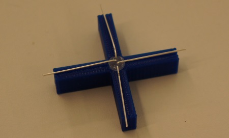
The star-shaped jig for bending LEDs improves efficiency and alignment. An interesting observation is that the LED can be inserted in any orientation. The only unbendable rule for lead bending is the order: up, left, right, down. By the 64th LED, you have reached an amazing speed.
Next comes wires.

Ordinary fence wire won’t line anyone’s pockets, but works perfectly. It needs a bit of straightening out before it can be trusted with the task we have in mind, though. The process is simple: pull firmly, without yanking, and watch it stretch. Best done in pairs.

Cut to measure. Length is not too important, just keep it over 10cm.

Three people made about 700 of these. We got the hang of it after about 100.
In addition to LED bending and wire stretching, we had USB cables, Arduinos and 3D-printed jigs for 10 people.
 DAY 2: ASSEMBLY
4 LEDs and two wires goes into the soldering jig. The topmost LED can be put in at any orientation, but each LED downwards must then be rotated 90 degrees clockwise. Bring out the old soldering iron and link the connections before the heat makes the wire dig itself into the plastic jig (according to our jig maker, this never happens to him).

Then, use the removal tool, turn the LEDs 180 degrees and repeat for the other leads.

It helps to have the PCB rigged with the Arduino and 4 temporary connectors, to confirm the non-presence of dud soldering joints.

When happy, clip the wings.

The 16 towers with a total of 256 soldering joints is a great way to improve soldering skills for novices. For everyone else, it is a great way to test one’s patience.
Before assembly, solder the SMT header to the PCB. This is where the Arduino Nano will go. The reason for using surface mount headers is to avoid visible solder joints on the top.
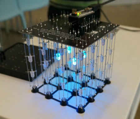
To assemble, put the PCB in the base and stick all 16 towers in it without soldering. Take care to ensure that all towers are oriented the same way by matching the orientation of the topmost LED. Put the hat on top and turn it all upside down. It is now possible to adjust the height/level of the PCB and make sure it is completely flat. Also make sure that all towers are fully extended into the hats and not suspended in the air.
Then solder the last 64 joints and hope for the best.

As a last step, cut the protruding wires, and.. Voila!
I can’t wait to make som impressive sequences for this, watch this space for the obligatory scroll text program next.